Concrete Mixer Pump Parts: Key Components and How They Work
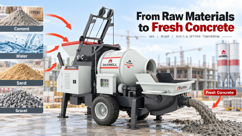
A concrete mixer pump performs two tasks: mixing raw materials into a uniform concrete blend, then transporting that concrete through a pipeline to the designated pouring location.
To finish these two steps, the various components within the concrete mixer pump must work in coordination, each performing its specific function:
The mixing blades ensure the raw materials are thoroughly blended, the concrete piston pushes the material forward, the S-valve controls the direction of concrete flow, and the hydraulic system provides the power for the entire pumping process. Ultimately, a complete concrete mixer pump’s production and transport line was assembled.
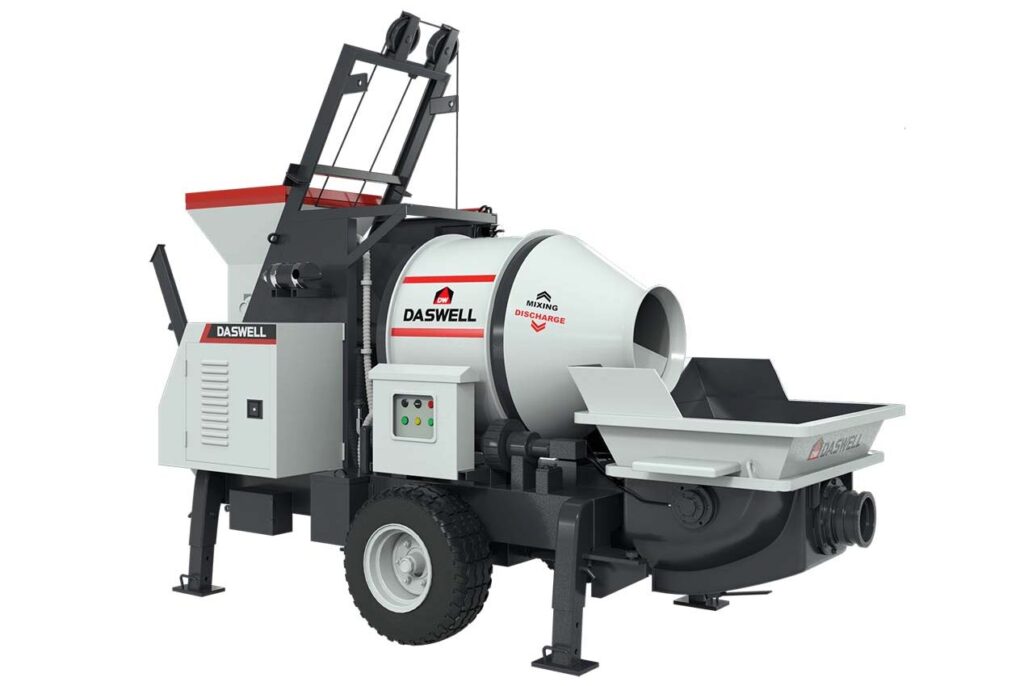
What components make up a concrete mixer pump?
A concrete mixer pump is not merely a combination of a mixer and a concrete pump. To ensure a seamless workflow—from the mixing of raw materials to the final pouring of the concrete—multiple systems within the equipment must operate in coordination.
| Systems | Key Components | Function |
| Mixing system | Feeding hopper, mixing drum, mixing blades, mixing shaft and drive mechanism | Thoroughly mix the raw materials |
| Pumping system | Concrete delivery cylinder, piston, S-valve and swing mechanism | Draw in and propel concrete |
| Hydraulic system | Hydraulic pumps, hydraulic cylinders, control valves, oil pipes | provide and control driving force |
| Power system | Diesel engine or electric motor | Provide power for equipment operation |
| Control system | Control panels, relays, sensors, and related electrical components | coordinating mixing and pumping operations |
| Delivery system | Concrete delivery pipes, elbows, hoses, pipe clamps, and sealing rings | Transport the concrete to the placement location |
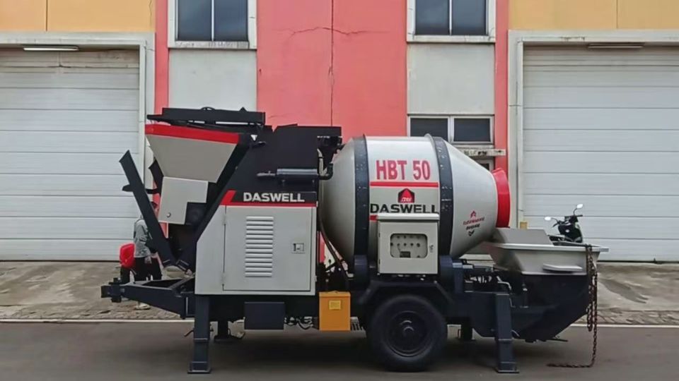
A typical drum type concrete mixer pump unit consists primarily of the following six components. The equipment is also equipped with a frame, wheels, support devices, lubrication components, and necessary safety protective structures. In addition to the drum type mixing mechanism, some models utilize a twin-shaft forced mixing mechanism.
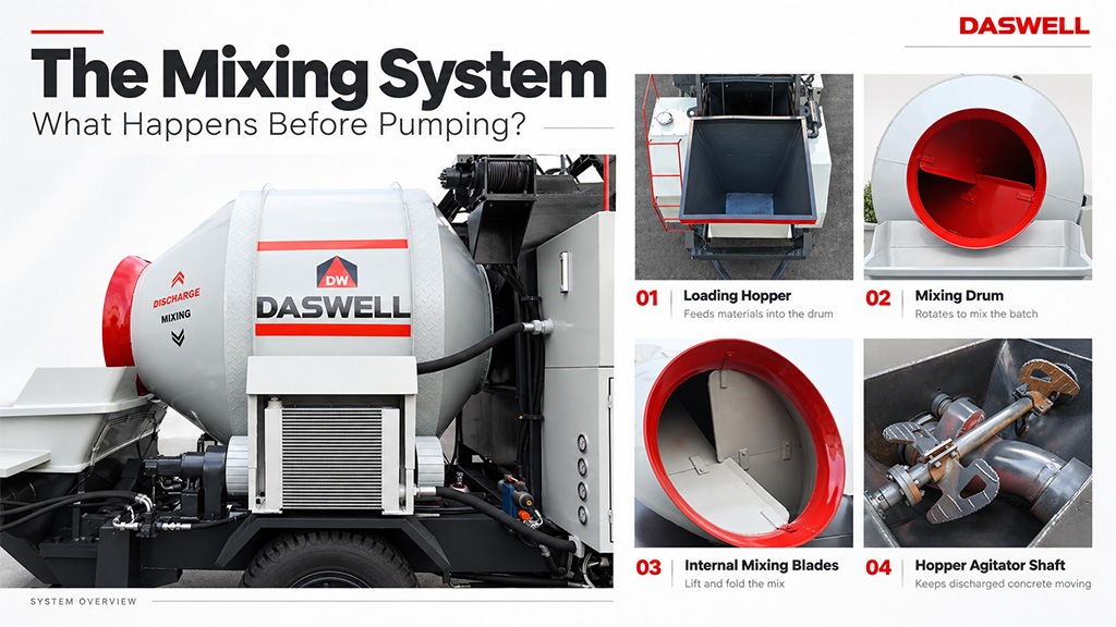
Mixing System: How Concrete Is Prepared Before Pumping?
The mixing system marks the beginning of the entire workflow. Various raw materials are thoroughly blended according to a predetermined mix ratio, ensuring that the cement paste uniformly coats the aggregates to produce concrete suitable for subsequent pumping.
1. Skip Hopper
In a concrete mixer pump, materials such as sand, aggregate, and cement are first loaded into a feed hopper, from which they are transported into the mixing drum via a lifting mechanism.
The feed hopper is constructed from steel and must withstand the impact and friction resulting from the repeated loading and unloading of sand and aggregate. In actual construction operations, the feed hopper serves to transfer materials and dictates the rate at which materials are supplied to the mixing equipment.
2. Mixing Drum
Once cement, aggregates, and water enter the drum, the drum’s rotation lifts, tumbles, and redistributes the materials, thereby achieving a thorough mix.
Unlike forced-action mixers, drum-type mixers rely primarily on the lifting and tumbling motion of the materials—generated as they rotate along with the drum—to facilitate mixing. The structural design of the mixing drum, its effective capacity, and the arrangement of its internal blades all influence the efficiency of the concrete mixing process.
3. Mixing Blades
If the mixing drum provides the space for blending, then the mixing blades serve as the essential components that drive the movement of the materials.
As the drum rotates, the internal blades lift the concrete raw materials to a certain height, allowing them to fall back to the bottom of the drum under the force of gravity. Through the continuous repetition of this process, the cement paste, fine aggregates, and coarse aggregates are gradually mixed into a uniform blend.
4. Mixing Shaft and Drive Components
In configurations that utilize a mixing shaft, the shaft serves to transmit torque from the drive mechanism to the mixing components. In the case of drum-type equipment, a transmission mechanism is also required to drive the rotation of the drum.
These assemblies typically comprise components such as a drive motor, a transmission mechanism, bearings, and various connectors. Bearings support the rotating parts and reduce motion resistance, while the connectors must withstand the torque and vibrations generated during equipment operation.
Pumping System: How Concrete Moves Through the Pump
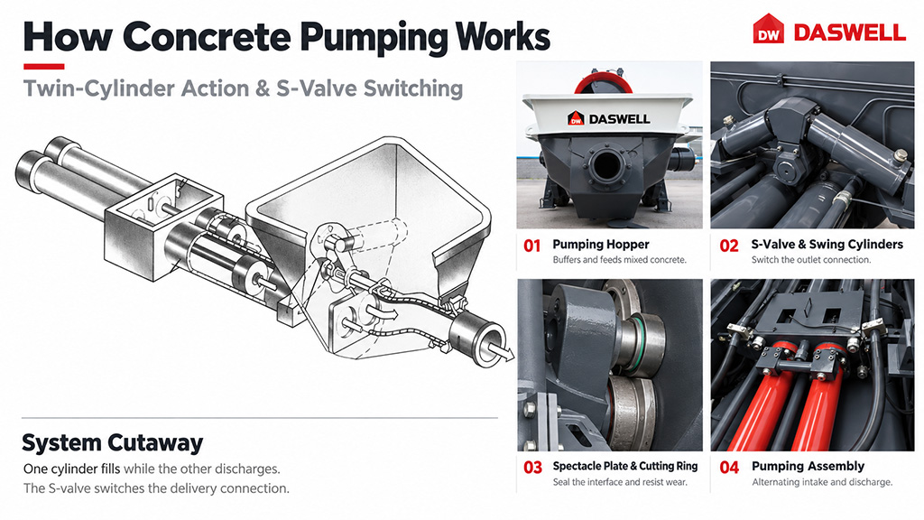
After mixing, the next step involves discharging the material from the mixing system into a pump hopper, transferring it into a sealed conveying pipeline, and propelling it forward through the pipe via applied pressure.
This process is primarily carried out by the concrete conveying cylinder, concrete piston, S-valve, and their associated drive mechanisms.
1. Concrete Pumping Hopper
The pump hopper is positioned between the mixing system and the pumping system; it serves primarily to temporarily store the mixed concrete and provide a continuous supply of material to the delivery cylinders.
Some hoppers are also equipped with an agitation mechanism and a protective grid, which help minimize concrete segregation and prevent the entry of foreign objects.
2. Delivery Cylinder & Piston
In a twin-cylinder piston-type configuration, the equipment is typically equipped with two concrete delivery cylinders, each containing a concrete piston capable of reciprocating motion.
The back-and-forth movement of these pistons creates suction or compression, allowing the two cylinders to operate alternately: while one cylinder draws in material, the other discharges material into the pipeline.
3. S-Valve & Swing Cylinder
The S-valve typically features a curved, tubular structure. Its primary function is to manage the connection between the two concrete delivery cylinders and the discharge pipeline, ensuring that the concrete is directed into the delivery line as intended.
An oscillating hydraulic cylinder—connected via a mechanical linkage—drives the S-valve, enabling it to toggle between its two operating positions. During standard operation, this oscillating cylinder must execute its movements in strict accordance with commands issued by the control system.
4. Wear Plate and Cutting Ring
The wear plate is typically installed where the pump hopper connects to the delivery cylinders; it is named for its appearance—resembling a pair of eyeglasses—due to the two openings that align with the delivery cylinders. The cutting ring is mounted at the inlet end of the S-valve, forming a mating surface with the wear plate that provides both a seal and resistance to wear.
These two components serve two primary functions: first, they maintain the necessary seal between the S-valve and the inlets of the delivery cylinders, minimizing the leakage of concrete paste at the interface; second, they withstand the friction and shearing forces exerted by the concrete aggregates during the switching process of the S-valve.
Hydraulic System: What Powers the Pumping Process?
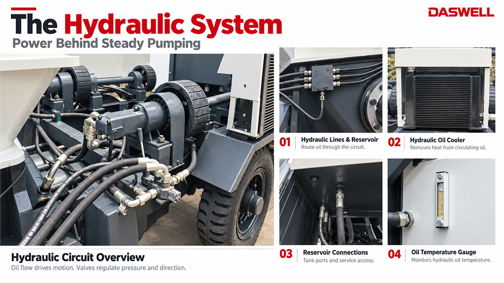
In hydraulically driven concrete mixing pumps, the significant mass of the concrete and its inherent flow resistance necessitate the application of sufficient propulsive force—a task primarily handled by the hydraulic system.
1. Hydraulic Pump
A hydraulic pump draws in hydraulic fluid through mechanical drive and delivers it into a hydraulic circuit at a specific flow rate. When the fluid encounters resistance from a load within the circuit, the system builds up pressure, which in turn drives the movement of a hydraulic cylinder.
2. Main Hydraulic Cylinder
In a typical twin-cylinder hydraulic piston-type concrete pump, the main hydraulic cylinders correspond to the concrete delivery cylinders, with motion transmitted between them via connecting mechanisms such as piston rods.
3. Hydraulic Control Valves
Hydraulic control valves are responsible for regulating the flow direction, pressure, and flow rate of hydraulic fluid.
Pressure control valves are used to limit or regulate the pressure within a hydraulic circuit, preventing the system from experiencing pressures that exceed design specifications under abnormal load conditions.
4. Hydraulic Hoses and Oil Tank
Hydraulic hoses and pipes connect the hydraulic pump, control valves, and hydraulic cylinders, allowing hydraulic fluid to circulate between these components. The hydraulic reservoir stores the fluid and facilitates its circulation, heat dissipation, and the separation of air bubbles.
Power System: Diesel Engine vs. Electric Motor
Concrete mixer pumps require a continuous power input to drive the mixing mechanism, hydraulic pumps, and other auxiliary systems.
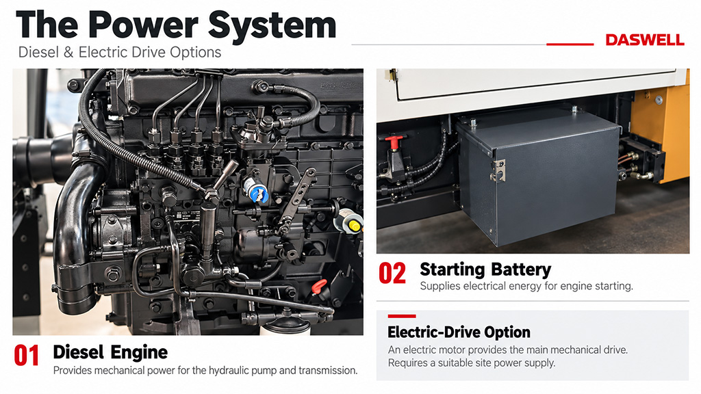
By power source, our concrete mixer pumps are available in two versions: those powered by a diesel engine and those powered by an electric motor.
1. Diesel Engine
A diesel engine consists of a fuel supply system, an air intake system, a cooling system, a lubrication system, and a starting system. It generates mechanical power through the combustion of diesel fuel, which in turn drives hydraulic pumps and associated transmission mechanisms.
For rural construction sites, remote areas, or temporary work sites where power supply options are limited, a diesel-powered concrete mixer pump offers a high degree of operational independence.
2. Electric Motor
Electric-powered concrete mixer pumps derive their mechanical power from an electric motor.
Compared to diesel engines, electric motors eliminate the need for on-site fuel combustion; they generally operate with lower noise levels and provide a more stable power output. For construction sites with a reliable power supply, electric-powered equipment reduces the need for fuel replenishment.
Control System: How Different Components Work Together
The various systems within a concrete mixer pump do not operate independently. The control system coordinates the different components.
1. Control Panel
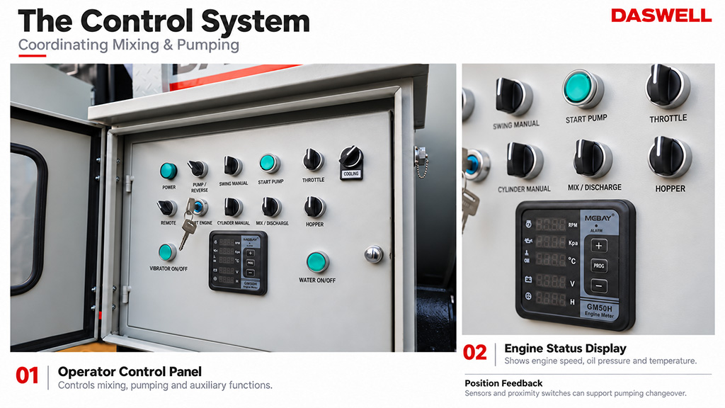
Through the control panel, operators can manage the mixing and pumping functions, as well as monitor essential operational status.
Some equipment also includes features such as forward and reverse pumping. Forward pumping is used for the standard transport of concrete, while reverse pumping allows the pumping mechanism to operate in the opposite direction—a function that, under appropriate conditions, can help alleviate localized blockages or address pumping irregularities.
2. Sensors and Proximity Switches
Sensors provide feedback on the operating status of the concrete mixer pump to the control system.
In hydraulic piston-type concrete pumps, certain proximity switches or position-sensing components are used to identify the travel positions of specific mechanisms, thereby providing control signals for the switching of the pumping cycle.
Delivery System: How Concrete Reaches the Pouring Point?
After exiting the S-valve, the concrete must travel through a delivery pipeline to reach the construction site.
During this process, the delivery system is subjected to the pressure exerted by the concrete, friction from the aggregates, and vibrations generated during equipment operation.
1. Concrete Delivery Pipes
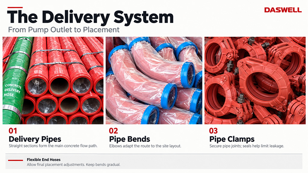
Concrete delivery pipes serve as the primary conduit between concrete mixer pump and the placement site.
Depending on the specific conditions of the construction site, personnel can configure various delivery routes by combining straight pipes, elbows, and other connecting components.
2. Pipe Clamps and Sealing Rings
Pipe clamps are used to join adjacent concrete delivery pipes, forming a continuous pipeline. Sealing rings are installed at these connection points to minimize the leakage of concrete paste.
3. Flexible Delivery Hose
Flexible delivery hoses are commonly used in construction areas where the concrete placement position needs to be adjusted frequently. Compared to rigid steel pipes, these hoses allow for easier changes to the discharge direction at the outlet end.
Wear and Replacement of Parts for Concrete Mixer Pump
The following are common critical wear parts and the signs of their wear.
| Parts | Common Signs of Wear or Abnormalities | Potential Impacts |
| Concrete piston | Wear and deformation of sealing surfaces | Reduced pumping efficiency, slurry leakage |
| Wear plate | Contact surface wear, grooving | Reduced sealing effectiveness, material backflow |
| Cutting ring | Wear of contact surfaces, increase in clearance | Degraded sealing performance of the S-valve |
| Mixing blade | Blades become thinner, and edges show wear | Reduced mixing efficiency |
| Delivery cylinder | Wear and scratching on the inner wall | Deterioration of piston sealing performance |
| Pipes and pipe bends | Thinning of the pipe wall, localized damage | Increased risk of leaks and pipeline failure |
| Pipe sealing ring | Aging, compression set | Joint leakage |
🟢 Confirm the equipment model 👉 Verify the technical specifications of the components 👉 Pay attention to the materials and wear resistance of the components
How Do All Concrete Mixer Pump Parts Work Together?
Let’s take a look at a complete operational cycle of the concrete mixer pump through a video.